A common manipulation in the daily work of a dentist is the direct restoration of lateral teeth. The most labor-intensive operation is considered to be modeling of the occlusal surface. This work requires the use of additional tools and adherence to the technique of adding material in small portions, but even in this case it does not always guarantee an ideal result. Popular proprietary methods for restoring lateral teeth cannot be called perfect. We present to your attention a simplified technique that allows you to perform aesthetic restoration simply, quickly and predictably.
Advantages and features of simultaneous modeling
The occlusion of teeth differs in individual characteristics for each patient - the cusps can be flattened, strongly pronounced, etc. In the case where a tooth is affected by a carious process or there is a voluminous restoration, it is very important to determine the anatomy of the surface that was before the destruction of tissue by caries. To do this, it is necessary to perform an analysis of the preserved tissues and then restore the anatomical picture: the severity and depth of the tubercles, the location of fissures and depressions. This information will allow you to carry out a tooth restoration that matches your individual anatomy.
Principles of technology:
- Simultaneous application of the material in small portions makes it possible to accurately repeat the occlusion of the tooth;
- Simulation is only available for a certain cavity size;
- The following information is used to reconstruct a picture of the tooth anatomy:
— inspection before preparation;
— inspection of residual, undamaged tissue after filing;
— examination of adjacent teeth and antagonists.
Advantages of the technology:
- High restoration speed. Simultaneous application of the material in several portions reduces the multiplicity of polymerization;
- Simplification of restoration. Distributing the material towards the center of the surface will require less corrective work in the future;
- Preliminary analysis. The technology allows you to analyze, check and adjust the location, features and inclination of the restored structures before polymerization;
- Shrinkage control. The stress factor (tension) in the composite is controlled through repeated application of the material.
- Standardized technology. The standard cavity depth (dimensions below) makes the technique reproducible in many clinical cases.
The only limitation is the absence of marginal ridges - if there is significant tooth decay, this technique is impractical.
Material and methods
The study used extracted permanent, fully formed molars, as well as a skeletonized human mandible with teeth. The teeth had no foci of carious lesions and had not previously been treated for this disease or its complications.
To study the structure and localization of the coronal cavity of the studied teeth, data from cone-beam computed tomography were used, which was carried out on a NewTom 3G device (QR srl, Verona, Italy). The characteristics of the tomograph met the following requirements: detector diameter (inches) - 12"; detector field of view (maximum field of coverage) (mm) - 200; pixel dimensions (mm) - 0.22; reconstruction field of view (mm) - 215* and 184** (* - enlarged pixel; ** - reduced pixel); reconstruction diameter (mm) - 215 and 184; pixel sizes in axial sections (mm) - 0.42 and 0.36; reconstruction cut thickness (mm) - 0.2-5; noise (%) - 2.6; scanning time (s) - 36.
The X-ray generator of the computed tomograph operated in the following mode: maximum voltage 110 kV for all modes; X-ray generator frequency 150 KHz; maximum current 15 mA; The radiation dose reduction program was selected automatically depending on the size of the object under study.
The tomograph's safe scanning program (autoexposure) operated on the principle of controlling the exposure time depending on the data received by the detector.
The radiation dose to the object under study (fields 12"/9"/6") corresponded to the lowest effective dose among volumetric tomographs - ½.5/4/mGy
The positioning of the object under study assumed a horizontal position, as well as the use of a dual laser guidance system and corresponding software.
To carry out an adequate comparison of data at the planning stage, as well as to build an accurate virtual model, tomography was carried out according to the following parameters: slice size (slice) 0.5-1 mm, Gantrytilt angle (Gantrytilt) 0°.
The obtained data were converted and stored on digital media in DICOM format for further engineering and mathematical processing.
To conduct cone beam computed tomography (CBCT), the extracted teeth were plastered in special cuvettes to the level of their coronal part. A skeletonized jaw with teeth was used for the same purpose without any additional fixation.
To obtain digital data on the anatomical features of the structure of the coronal part of the molars used in the study, plaster models of them were made, which were subsequently subjected to surface laser scanning. For this purpose, a 3SHAPE D900 scanner (3M, USA) was used. The parameters of this device include: number of cameras - 4; recorder technology - blue LED; error - 15 microns (*accuracy determined using a calibrated standard); texture scanning - color textures; scanning time - 15-85 s; scanning using DentalSystemPremium. The obtained data was saved on digital media in STL format for further planning or mathematical processing.
The coronal portions of teeth in a skeletonized human mandible were directly surface scanned, allowing the procedure to be simulated in a clinical setting using an intraoral scanner.
Stereolithography was used to produce various endodontic template models. The templates were printed using laser stereolithography using an LS-250 installation (IPLIT, Shatura RF), which has a printing accuracy of 0.1 mm and a roughness of 20 microns. Also for this purpose, an Objet printer was used - Eden500V (Stratasys, Minnesota, USA), which has the following accuracy parameters:
— resolution along the X, Y axes — 600 dpi, z — 1600 dpi;
— layer thickness in “HQ” mode — 16 microns;
- relative accuracy when printing a 50 mm prototype along one of the axes is 20-85 microns.
Computer modeling of three-dimensional endodontic templates was carried out using 3dsMAX 2009 software (Autodesk, USA).
Specialized software Amira 4.1.2 (VisualizationSciencesGroup, MercuryComputerSystems, USA) was used to process digital CBCT data and surface scanning of teeth and plaster models. To perform endodontic manipulations, the following were used: a cylindrical turbine bur with diamond chips at the end and special turbine burs designed to open the dental cavity.
Description of technology
Knowledge of tooth anatomy plays a leading role in the success of restoration. Information is collected before work begins (analysis of the restored and adjacent teeth with determination of the anatomical features of the elements). 1. Restoration begins with preparing the bottom of the cavity. The required depth is 1-2 mm relative to the height of the marginal ridge.
The bottom of the cavity is slightly rounded or flat. With the specified cavity depth and an average distance of 3-3.5 mm from the top of the buccal cusp to the base of the fissure, structures can be precisely formed in the required volume.
The choice of composite material for cavity formation depends on the specific clinical case. As for the thickness of the tubercles: it is usually equal to or greater than 2 mm. If the value is lower, indirect restoration is advisable.
2. cusp ridges
To better determine the volume ratio, the first portions of the material are applied simultaneously, corresponding to each hillock.
Portions of material are distributed from the periphery to the central part so that the area of the slopes of the mounds is increased. These parts of the material should not be connected; complete closure of the surface is performed at the final stage.
Excess material is removed with an instrument along healthy tissue.
Before polymerization, the final correction of the ridge is performed. The composite is adjusted along the edges using a brush.
3. Extreme rollers
The distal and medial ridges are restored in the same way. The composite is added in small portions and distributed over the surface using a tool; excess is removed by moving an umbrella near healthy tissues. Correction of the position of the composite is performed with a brush.
4. Closing the cavity The central gap is filled with small portions of the composite and compacted to achieve the correct relative position of the surface structures. Portions of the material are adapted to the elements that have undergone polymerization to obtain an aesthetic deepening. The material is compacted with tools or a brush until it connects with the polymerized part. The grooves are refined with pointed instruments and after that polymerization is performed.
Closing the cavity can be done in several ways:
- By expanding the top of the tubercle (a minimum of material is taken);
- Expansion of the outer ridges;
- Adding an oblique ridge (for restoration of maxillary molars);
- By adding or expanding secondary tubercles.
5. Small cavities This technique is also applicable to small cavities. To form small areas, one edge is first modulated and then polymerized. In order for the fissure to have a natural appearance, a drop of material is modeled with a polymerized one located nearby.
Stress factor
It is known that all methods of layer-by-layer restoration of teeth are associated with a stress factor. But studies have proven that portioned restoration gives better results compared to others. Stress relates more to the volume of restoration than to the stress factor itself. When a composite is polymerized in one batch rather than in layers, the stress in the material is greater. In addition, the direction of shrinkage affects both adhesion areas and free areas. Applying the material simultaneously, which is proposed in this technique, allows us to take into account all the difficulties and eliminate the polymerization stress factor as much as possible at all stages of restoration.
Variant of the direct method modeling technique for the occlusal surface of lateral teeth
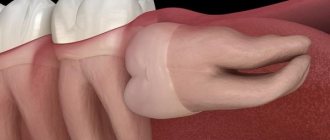
The results of studies on the structural features of the lateral teeth, and in particular their occlusal relief, formed the basis for the development of a variant of the technique for modeling their occlusal surface. The essence of the proposed technique is that the modeling of the tubercles and the relief of the occlusal surface is performed according to the “envelope” principle. In this case, the restoration is carried out with the sequential restoration of the opposite tubercles. We propose to take into account two clinical situations: a) destruction of the occlusal surface of the lateral teeth while maintaining the height of the tubercles; b) complete destruction of the occlusal surface of the lateral teeth. Restoration of the occlusal surface with its complete destruction was carried out in 11 patients on 5 premolars and 7 molars, and while maintaining the height of at least one cusp - in 9 patients on 4 premolars and 5 molars. The modeling stages are presented in diagrams (Fig. 2, 3, 6, 9) and clinical cases (Fig. 4, 7, 8). For restorations, light-curing composites Filtek P-60, Filtek Zet-250 and Filtek flow (3M/ESPE) were used in compliance with the instructions for their use.
Stages of modeling the occlusal surface of the first upper molar with its complete destruction
1. Study of interocclusal relationships, relief and structural features of the “oblique ridge”.
Before starting restoration, for a more detailed study of the occlusal relationships between the dentition, and in particular between a tooth with a destroyed occlusal surface and antagonists, it is advisable to take impressions and make diagnostic models from high-strength plaster to prevent possible abrasion of individual relief details in the process of studying the models. Using diagnostic models, the individual characteristics of the orthognathic bite, interocclusal relationships in the area of the lateral and anterior teeth, the degree of overlap of the lower anterior teeth with the upper ones, as well as the topography of occlusal contacts are determined. Particular attention is paid to the study of occlusal relief and the structure of the “oblique ridge”. In the absence of the possibility of producing diagnostic models, the above criteria can be determined in the oral cavity. Using articulation paper (for example, Bausch), the topography of occlusal contacts on an irrationally restored occlusal surface is studied, as well as the presence or absence of vertical displacement of the teeth. In case of complete destruction of the occlusal surface, it is necessary to determine the projection of the vestibular distal (median) tubercle of the first lower molar in relation to the destroyed surface of the antagonist tooth. With the help of functional tests, the degree of disocclusion should be studied during movements of the lower jaw in the sagittal and transversal planes - as a guide to a certain relationship between the depth of overlap of teeth in the frontal area, the height of the cusps of the lateral teeth and occlusal curves. The more pronounced the frontal overlap of the teeth, the more pronounced the height of the cusps of the lateral teeth and the sharper the occlusal curves. If non-functional occlusal contacts are detected, they should be eliminated by selective grinding before starting treatment.
2. Determination of the color of the restoration using a shade scale of the composite material.
3. In the presence of a tooth defect that cannot be attributed to any of the Black classes, we followed the technique of constructing a lateral tooth, taking into account the biomimetic principle, proposed by S.V. Radlinsky. (1996, 1999, 2000). Using this technique, the restoration of lateral teeth begins with the oral and vestibular walls, then the contact surfaces are built, and the middle remains empty until all vertical walls of the crown are completely built. In this technique, the labial and oral walls act as the main positioners of the crown, which can be compared to the “marks” used to create a level when laying ceramic tiles. Thanks to the construction of “marks,” we consistently transform an arbitrary crown defect into a MOD defect—medial-occlusal-distal. With the construction of the proximal distal contact wall, the crown defect from the MOD is transferred to the MO defect—medial occlusal. At the same time, through the free central space, not filled with filling material, the light of the polymerization lamp penetrates more easily, which ensures better polymerization of the proximal walls of the restoration. Next, the medial contact wall is performed, transferring the defect to O - occlusal.
4. Modeling of the medial vestibular tubercle with preliminary determination of its height along the tooth of the opposite side of the dental arch and orientation to the height of the crown of the second premolar on the working side.
If there is no preserved height of the tubercles on both sides, restoration is carried out according to the average height of the tubercles. Since the vestibular surface of the medial tubercle is more convex than the distal one, we form it with two separate portions of material. After the first layer, we outline the longitudinal ridge and its slopes on the occlusal surface, and then complete the modeling of the vestibular surface of the tubercle at the base. For correct spatial orientation when constructing tubercles, as suggested by Vetchinkin A.V. (2002), modeling is carried out taking into account three main lines: the line connecting the tops of the vestibular tubercles, the line of the central groove of the occlusal surface and the line connecting the tops of the oral tubercles.12
5. Modeling of the vestibular distal tubercle and the formation of the vestibular groove (the border of the odontomeres) with its transfer to the occlusal surface to the center of the crown. Its depth and extent varies widely.
6. Modeling of the medial palatal tubercle and transverse enamel ridge - “oblique ridge”.
Using a separate portion of material, we form the palatal surface of the tubercle and outline its future apex so that it is in line with the top of the distal vestibular tubercle. The medial ridge is smoothly transformed into a fairly pronounced medial marginal ridge, and the distal one is connected in the central part of the chewing surface with the ridge of the longitudinal ridge of the distal vestibular tubercle. Thus, the distal surface of the “marginal ridge” is formed, which divides the occlusal surface of the crown into two unequal parts. Next, we model the ridge of the longitudinal ridge, medial and distal slope from the top of the tubercle to the center of the chewing surface. At the junction with the longitudinal ridge of the medial vestibular tubercle, a central groove is formed. The distal slope of this tubercle, through the resulting transverse groove, coinciding with the line of the largest diagonal from the vestibular-medial edge to the distal-palatal one, is connected to the medial slope of the distal vestibular tubercle.
If there is significant destruction of the palatal surface of the crown, the Carabelli tubercle is restored with a separate portion of material.
7. Modeling of the medial accessory tubercle and formation of the anterior central (triangular) fossa.
8. Modeling of the lowest distal palatine tubercle, additional distal tubercle and formation of the posterior central (triangular) fossa with the distal palatal sulcus.
9. Determination of the nature of the closure of the restored tooth with antagonist teeth, localization of occlusal contacts using articulation paper (for example, Bausch), their correction in central and functional occlusion.
10. Finishing the restoration.
Stages of modeling the occlusal surface of the first upper molar while maintaining the height of the cusps
The principles and sequence of modeling in such clinical situations follow the rules described above, taking into account the number of remaining cusps and the occlusal surface pattern characteristic of the tooth.
An example of restoration of the occlusal surface of tooth 26 while maintaining the height of the cusps
Stages of modeling the occlusal surface of the first lower molar with its complete destruction
1. Study of interocclusal relationships, relief and determination of the type of pattern on the first lower molars.
Before starting restoration, it is necessary to study the occlusal relationships between the dentition, and in particular between the first molars on the side of the affected tooth. In case of a destroyed, irrationally restored occlusal surface of a symmetrical tooth or its absence, it is necessary to determine the place of occlusal contact of the medial palatal tubercle of the upper antagonist molar. In such cases, we recommend restoring the occlusal surface of the tooth with the simplest pattern in the form of a plus sign (“+”). Normally, a pattern in the form of a “plus” sign is characterized by the presence of one central fossa, with which, in the position of central occlusion, the medial lingual cusp of the upper molar antagonist forms occlusal contact. Patterns in the form of the letter “Y” (“Y”) and the letter “X” (“X”) are characterized by the presence of a medial and distal central fossa. With these types of patterns, the medial lingual cusp forms an occlusal contact in the area of the distal fossa. It follows from this that the location of the occlusal contact formed by the medial lingual cusp can serve as a guide for optimal restoration of the destroyed chewing surface of the lower first molar to its original state. This will allow you to create more accurate occlusal intertubercular relationships and choose an individual restorative treatment plan in each clinical case. Thus, depending on the type of pattern, we will take into account their characteristic features during modeling. During the biometry of the models, the presence or absence of tooth migration and the nature of the overlap of the lower teeth with the upper ones in the frontal area were also determined.
2. Determining the color of the future restoration using the VITA Classic color shade scale.
3. Construction of the supporting parts of the crown with separate portions of restoration material and transfer of the defect from arbitrary to MOD (medial-occlusal-distal).
4. Transfer of the MOD defect to the MO (medial-occlusal). Installation of a sectional matrix and wedge to construct a proximal-distal contact point. Contact points on the lateral teeth are located closer to the vestibular surface, and the lingual proximal surfaces are turned toward the oral side. To properly construct the contact point, the wedges must be installed on the lingual side.
5. Transfer of the MO defect to O (occlusal). Installation of a sectional matrix and wedge with the construction of a proximal medial contact.
6. At this stage, regardless of the type of pattern, based on the principles of shaping tooth crowns from odontometer modules proposed by L.M. Lomiashvili, L.G. Ayupova. (2004), we begin modeling the chewing surface from the vestibular distal tubercle, which occupies the central position of the vestibular part of the molar, with a preliminary determination of the height of the crown based on a symmetrically located tooth. If there is no preserved height of the tubercles on both sides, restoration is carried out according to the average height values of the odontometer. The formation of the medial border of the vestibular surface of the tubercle should be carried out at an average distance of about 5 mm from the medial corner of the crown with an inclination towards the lingual side, leaving space for modeling the medial vestibular tubercle. We form the distal border of the tubercle at a distance of about 4 mm, leaving 2 mm for the distal tubercle, which corresponds to the average values of the mesial-distal size of the crown according to odontometry data of the permanent first molar of the mandible. In this way we simultaneously establish the boundaries of three vestibular tubercles and two sulci, of which the medial vestibular sulcus is slightly longer and more pronounced than the distal vestibular sulcus.
7. Depending on the type of pattern, with a pattern in the form of a “plus” sign, we proceed to modeling the lingual distal tubercle. This tubercle is restored higher and sharper than the distal (posterior) one. The medial border of this cusp (lingual sulcus) is formed at the level of the medial vestibular sulcus with the formation in the central part of the crown of one central fossa or common point of contact between the cusps. Next, we model the vestibular medial tubercle using sequentially separate portions of material. We model it as a more massive tubercle using existing additional anatomical landmarks - the distal vestibular and medial lingual tubercles. An additional cusp is often located between the medial vestibular and medial lingual cusps.
With a pattern in the form of the letter “X” (“X”), the lingual distal tubercle is modeled in such a way that the longitudinal ridge of this tubercle intersects diagonally the central part of the crown in the direction of the vestibular medial tubercle, where a straight line should be formed between it and the lingual distal tubercle. contact not separated by a groove. Next, we carry out sequential modeling of the vestibular and lingual medial tubercles in separate portions of material.
With a pattern in the form of the letter “Y”, the medial lingual tubercle is modeled, which, with its pronounced longitudinal ridge, connects through a short groove in the central part of the crown with the distal vestibular tubercle, dividing the occlusal surface into two parts. Next, we sequentially construct the lingual distal and vestibular medial tubercles using separate portions of material. After this, we model the lingual medial tubercle. The lingual medial tubercle is slightly higher and larger than the lingual distal one, and also higher and sharper than the medial vestibular one. The angle formed by the slopes of the tubercles facing each other is close to straight. When modeling the lingual medial tubercle, an additional guideline for the correct formation of its medial border, according to our observation, can be an imaginary line drawn from the apex of the lingual tubercle of the second premolar to the medial central fossa of the first lower molar. Next comes the modeling of the additional medial tubercle.
8. Modeling the distal cusp is the final stage in modeling the occlusal surface of the first lower molar for all three main types of pattern.
9. Determination of the nature of the closure of the restored tooth with antagonist teeth, the topography of occlusal contacts using articulating paper (for example, Bausch), their correction in central and functional occlusion.
10. Finishing the restoration. This algorithm for modeling the occlusal surface of molars, in our opinion, allows not only to most correctly restore the lost anatomical relief, but also to perform directional polymerization using diagonal positions of the light guide.
Stages of modeling the occlusal surface of the lower first molar while maintaining the height of the cusps
In such clinical situations, a tooth crown defect can be described as a MOD (medial-occlusal-distal) defect, or a MO (medial-occlusal) and OD (occlusal-distal) defect, which must be converted into an O (occlusal) defect. After preparation and isolation of the surgical field from moisture, if there is not enough space between the teeth to install a sectional matrix and restore the contact point, it is necessary to first carry out separation preparation (“wedging”) using wooden wedges that are able to adsorb moisture and increase in volume. In the future, the basic principles and sequence of modeling are based on the above rules, taking into account the amount of tissue of the preserved tubercles and the pattern of the occlusal surface characteristic of a given tooth.
Stages of modeling the occlusal surface of the second molar of the mandible with its complete destruction
The basic principles and sequence of modeling are according to the rules described above, taking into account the pattern of the occlusal surface characteristic of a given tooth.
Subsequence:
1) modeling of the lingual distal tubercle;
2) modeling of the medial vestibular tubercle;
3) modeling of the lingual medial tubercle;
4) modeling of the vestibular distal tubercle.
Discussion of the results obtained
The anatomical shape of the first molars of the upper and lower jaws is one of the most complex in the dental system, and regardless of the method used to restore the defect in the coronal part of the tooth, the key point is modeling the relief of the occlusal surface. For each structural unit of the chewing surface, nature has its own function, and the features of the anatomical and morphological structure of these structural units determine the location of the occlusal contacts that maintain the height of the bite. Thanks to this fine differentiation, the working area of the chewing surface of the teeth is significantly increased, ensuring optimal performance of the function. Therefore, the stages of modeling the occlusal surface are based on the main anatomical features of the structure of the coronal part of the premolars and molars of the upper and lower jaws. Taking this into account, it is easier to plan the sequence of stages of modeling teeth with composite materials and eliminate possible errors made in the sequence of modeling the occlusal surface in each specific clinical case. Based on the above, a variant of the technique for modeling the tubercles and the relief of the occlusal surface of the lateral teeth was developed using the “envelope” principle, when restoration is carried out with the sequential restoration of the opposing tubercles.
It has been proven that always and in all cases each force must be balanced by another, equal in magnitude and opposite in direction, at every point of the structure. This statement is true for any structures that exist in nature, regardless of their size and complexity. If this condition is not met or changes for any reason, then under the influence of the load there is an imbalance between all elements of the structure, and over time - its destruction.16 Man is part of living nature, and the dental system is a complex of interconnected and interacting structural elements , ensuring the normally harmonious function of the entire structure. Considering the function of the dentofacial system from the point of view of the above, one can be convinced of the well-known fact that chewing pressure transmitted through the teeth to the lower jaw leads to the orientation of the crossbars of the cancellous bone tissue in a certain direction, according to local stresses, along the so-called trajectories. Collectively, the path lines of counter-loads create a frame-like structure and reflect the functional activity of the mandible. From the point of view of the theory of resistance, the lower jaw is considered as a body of equal resistance. 17, 18 It becomes clear that with regard to the structural features of the dentition, the most stable occlusion will be observed when the dental cusps come into contact with the fissures of the antagonists in the central occlusion, in which the greatest forces develop and, accordingly, , a function often used during chewing.19 As Novikov V. (2001) notes, this relationship between the cusps and marginal ridges is reminiscent of “brickwork,” the principle of which is that the bricks of each upper row are laid so that each of them overlaps the seam between bricks of the bottom row, which is optimal for evenly distributing the load and ensuring effective chewing. In addition, the morphological structure of the cusps of the lateral teeth is also of no small importance for the performance of the function of the dentofacial system. As S.V. Radlinsky points out,3 each tubercle of the chewing surface is shaped like a tetrahedral pyramid, the base of which has the shape of an irregular quadrangle and is located inside the dental crown, and the triangular faces form four ribs. One of them, located on the occlusal surface of the crown, is the most important from the point of view of chewing efficiency, since at a distance of 1-2 mm from the top of the tubercles there are occlusal contact points on it, which lead to the grinding of food, and the edges of the pyramid ensure the stability of the biostructure during the function. It can be assumed that this shape of the tubercles not only provides the function of grinding and chewing food, but also makes it possible to evenly distribute occlusal pressure along the ribs of the tubercles to the base of the pyramid, the level of which is located in the equator. In this case, the ribs are not only food crushers, but also “load crushers,” preventing overload of periodontal tissue along the long axis of the tooth. This assumption is confirmed by studies conducted by Boyanov B. and Raichev L.,20 which showed that when a tooth is loaded, stress spreads along the longitudinal axes or tangentially - at contact points between antagonist teeth.
The functional features of load distribution must be taken into account when modeling the masticatory surface tubercles, since occlusal contacts during chewing, not significantly different from those during swallowing, most often occur during sliding movements in different directions and from different starting points, thus forming occlusal areas during chewing and ensuring optimal performance of the function.19 The location and number of occlusal contacts, as well as the direction of the applied force during the closure of the teeth, affect the activity of the muscles that lift the mandible.21 Violations of occlusion lead to deformation of the occlusal plane, a change in the load on the elements of the temporomandibular joints , contributing to the development of chronic microtrauma and reflexively reducing the activity of the masticatory muscles. Only in the habitual closure of the dentition, free from disturbance, is their maximum activity noted.22
It has also been established that lateral teeth with a small distance between the vestibular and lingual cusps have less favorable conditions for normal transversal occlusion, taking into account the topographic position of the antagonists and the location of the axes of the teeth.23 From this it follows that with significant destruction of the tooth crown, when the main anatomical landmarks of the occlusal surface and there is no similar tooth with preserved morphology, when modeling the average anatomical dimensions of this tooth should be taken as a basis. This is necessary for more accurate restoration of the height of the tooth crown and its correct orientation in the dentition, which prevents destruction under the influence of chewing load in various planes.
The proposed version of the technique for modeling the occlusal surface of molars is based on the anatomical features of their structure, which, in our opinion, are guidelines for restoration, and only complements the known methods. For example, Radlinsky S.V. (1999) proposes to restore the occlusal surface with separate portions of restoration material, imitating individual cusps of the tooth, which with their boundaries will form a specific fissure pattern characteristic of a given tooth.3 According to V. Novikov (2001), one should focus on the preserved cusp tops and the main formation of the masticatory surfaces should be carried out after polymerization of the restoration material with special diamond burs of various grain sizes at the stage of finishing the restoration.9 Salova A.V., Rekhachev V.M. (2004) use a clinical example to demonstrate the restoration of tooth 46 and recommend that the buccal supporting cusps be restored first, then the lingual guides, and the weakened cusps be reduced in height by 2 mm and subsequently covered with a composite.10
Compliance with all stages of working with restorative filling material in the direct technique and modeling the occlusal surface is a complex task, difficult to accomplish without the use of a rubber dam or auxiliary tools (various types of roller holders) for maximum isolation of the restored tooth from contamination with saliva, etc. On the other hand, the larger the area destruction of the occlusal surface, the more difficult it is to achieve a positive treatment result without a specific modeling algorithm. This algorithm, on the one hand, should be easy to understand and remember, and on the other hand, it should be a “flexible tool” in the hands of the dentist, which could be easily adapted to various clinical situations, and would not change in its essence. In this case, a preliminary assessment of occlusal contacts and planning of the contours of future restoration are mandatory.24
Knowledge of the topography and anatomy of the occlusal surface of the lateral teeth will help to navigate the architectural features and correctly restore the tooth crown. Irrational filling, as well as prosthetics, which disrupts the maximum intertubercular contact, can contribute to the development of structural changes in periodontal tissues, cause chronic impairment of the activity of the masticatory muscles and lead to dysfunction of the temporomandibular joints (pain, clicking, crunching, etc.).25
conclusions
1. When modeling the occlusal relief of the lateral teeth, one should be guided by their individual architecture, that is, relief patterns.
2. A method for modeling the occlusal surface of lateral teeth using the “envelope” principle has been proposed, which provides the most accurate reproduction of the occlusal architecture.
Source: radlinskiy.ru
results
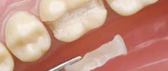
The use of the above research methods made it possible to develop the following algorithm of actions to achieve the goal: first of all, CBCT of the teeth of the upper or lower jaw (skeletal jaw with teeth) planned for endodontic treatment was performed. The obtained data was processed using computer viewing X-ray programs and a thorough study of the resulting digital image of the causative tooth (row of teeth) in direct and axial projections was carried out in order to detect and localize the boundaries of its coronal cavity (Fig. 1).
Rice. 1. CBCT of a skeletonized human lower jaw with teeth in axial projection. The coronal cavity of a molar is at the level of its roof.
Next, an impression was taken of the teeth requiring endodontic treatment using an impression mass and a plaster model was cast that accurately copied their crown parts. In the case of using a skeletonized jaw with teeth, this stage was skipped, taking into account the possibility of using an intraoral laser scanner in a clinical setting. The resulting model or skeletonized jaw was scanned with a 3SHAPE D900 dental scanner (3M, USA) to obtain a digital image of the crowns of the teeth under study (Fig. 2). Then, using the computer program Amira 4.1.2 (Visualization Sciences Group, Mercury Computer Systems, USA), digital images of the tooth obtained using computed tomography and scanning were combined. Then, using the computer program 3ds MAX 2009 (Autodesk, USA), a three-dimensional individual template was virtually modeled for the crown of the tooth, which had a hole strictly coinciding with the boundaries of the tooth cavity and projected onto its chewing surface (Fig. 3, 4, 6 ). Next, in the same way, a second template was modeled for the crown part of this tooth, which ensured the optimal depth of opening of the cavity. A small hole was modeled in the template, the projection of which was located within the boundaries of the tooth cavity. The template had a limiter, which was a hollow cylinder, through which a diamond bur was first introduced before contacting the coronal part of the tooth (Fig. 5, 8). It had a cylindrical shape and was covered with diamond chips only at the end of the working part (Fig. 9). When rotating and moving the bur deep into the tooth, it reached the bottom of the coronal cavity and stopped, since the bur shank rested against the limiter. Thus, the length of the limiter could be used to regulate the immersion depth of the drill.
Rice. 2. Digital image of the coronal part of the molars obtained using surface scanning. Anatomical features of the relief of the chewing surface of the teeth.
Rice. 3. The stage of virtual modeling of the endodontic template on the combined image obtained as a result of CBCT and surface scanning of the tooth. The module of the template corresponds to the volume of the coronal cavity of the mandibular molar. The lower border of the module is located at the level of the mouths of the root canals of the tooth.
Rice. 4. Modeled endodontic template, visualizing the required dimensions of the preparation of the coronal part of the tooth. The hole in the template exactly repeats the shape of the coronal cavity of the molar, projected onto its chewing surface.
Rice. 5. Endodontic template modeling stage. Formation of immersion limiters for a diamond turbine end bur designed to determine the depth of preparation of the coronal part of a molar.
Rice. 8. The shape of the endodontic template designed to visualize the depth of the coronal cavity of the molar.
Rice. 9. Endodontic template with an end bur inserted into it to determine the depth of the coronal cavity of the tooth.
The digital images of the templates were then converted by laser prototyping using a 3D printer into a product made of heavy-duty plastic.
In laboratory conditions, simulating the clinical stage of endodontic treatment of a molar, the first plastic template was placed on its coronal part and secured to it using an adhesive light polymerization system (Fig. 6, 7). Using a thin black felt-tip pen, the established contour of the tooth cavity was applied through the hole of the template onto the chewing surface of the crown of the tooth requiring endodontic treatment. We shot the first template. Then a second template was put on the same tooth and the coronal part was prepared through the hole in it with an end bur to the set depth (Fig. 8, 9). In this way, clear three-dimensional landmarks were formed for constructing optimal endodontic access. After removing the template, the tooth cavity was opened and its subsequent endodontic treatment was carried out using standard methods.
Rice. 6. Shape of the endodontic template reproduced using a 3D printer.
Rice. 7. Visualized boundaries of the coronal cavity of the lower molar after fixing the endodotic template on the teeth.
The advantages of the proposed method compared to traditional ones are: prevention of complications and errors during endodontic treatment of a tooth at the stage of opening the tooth cavity; preservation of hard dental tissues from excessive preparation in the process of searching for root canal orifices. The disadvantages of the method can be recognized as: the need for endodontic treatment of the tooth in several visits; additional costs for modeling and production of an individual template.